 en
en русский
 Español
 عربى
عربى
High-Efficiency Oil Removal for Compressed Air and Industrial Gas Systems
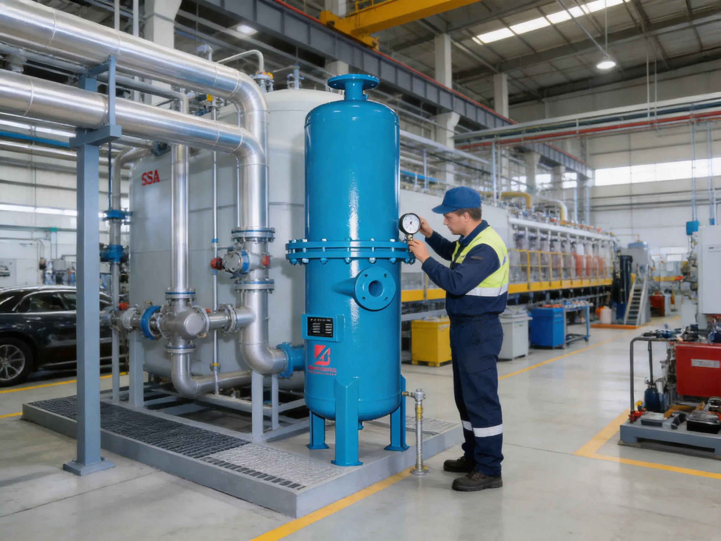
Compressed air is widely used as a power source and process medium in modern industry. It drives pneumatic tools, operates automatic valves, supports instrumentation, transports materials, and participates directly in manufacturing processes. However, compressed air is not automatically clean simply because it has been pressurized. Oil droplets, oil aerosols, condensed water, rust particles, pipe scale, and atmospheric dust can remain in the air stream after compression. If these contaminants are not removed, they may damage downstream equipment, reduce product quality, increase maintenance requirements, and compromise the reliability of an entire gas production system.
The high-efficiency oil remover described in this article is designed to address these problems through an integrated three-stage purification process. It combines cyclone separation, pre-filtration, and fine filtration in one treatment system. By using mechanical separation and progressive filtration, the equipment removes oil, water, and dust from compressed air while maintaining a comparatively low pressure loss. Under the stated operating conditions, the treated air can achieve filtration accuracy down to 0.1 micrometers, while residual oil content can be reduced to less than 0.01 parts per million in applicable operating conditions.
This type of equipment is particularly relevant to industrial air compressor systems, gas purification equipment, air separation units, and manufacturing processes that require stable and low-contamination compressed air. Its compact treatment concept, broad capacity range, and industrial construction make it suitable for applications ranging from small production lines to large centralized utility systems.
Content
- 1 The Importance of Oil-Free and Clean Compressed Air
- 2 Integrated Three-Stage Purification Principle
- 3 Key Performance Characteristics
- 4 Product Range and Capacity Selection
- 5 Advantages Compared with Single-Stage and Conventional Filtration
- 6 Manufacturing and Engineering Strengths
- 7 Applications Across Industrial Sectors
- 8 Installation Recommendations
- 9 Maintenance and Operating Practices
- 10 How to Specify the Equipment for a Project
- 11 Why Manufacturer Capability Matters
- 12 Q&A
- 12.1 What is the primary function of the high-efficiency oil remover?
- 12.2 What filtration accuracy can the system achieve?
- 12.3 What residual oil content is specified?
- 12.4 What operating pressure is supported?
- 12.5 What is the maximum inlet air temperature?
- 12.6 What pressure loss should users expect?
- 12.7 How should the capacity be selected?
- 12.8 Can the oil remover be used before a PSA nitrogen or oxygen generator?
- 12.9 Does the system eliminate the need for a dryer?
- 12.10 How often should the filter elements be replaced?
- 12.11 What information should be supplied when requesting a quotation?
- 12.12 Why is the three-stage design preferable to a single filter?
- 13 Conclusion
- 14 References
- 15 Product: BDC High-efficiency Oil Remover
The Importance of Oil-Free and Clean Compressed Air
Most lubricated air compressors use oil to lubricate bearings, cool internal components, and seal compression chambers. During operation, a small amount of oil may enter the compressed-air stream as liquid droplets, aerosols, or vapor. The quantity and form of this contamination depend on compressor design, operating temperature, lubricant condition, maintenance practices, and load profile.
Compressed air also contains moisture because atmospheric air naturally carries water vapor. When the air is compressed and subsequently cooled, part of the water vapor condenses. This condensate may combine with oil to form an emulsion that is difficult to remove using a single conventional filter. Dust and solid particles can enter from the ambient environment, while corrosion products and pipe debris may be generated within the compressed-air distribution network.
These contaminants can create several operational risks. Oil may foul pneumatic valves, interfere with instrumentation, reduce the performance of adsorption media, and contaminate products. Water can cause corrosion, freezing, paint defects, biological growth, and malfunction of pneumatic equipment. Dust and rust particles can block or abrade precision components. In food processing, electronics manufacturing, pharmaceutical production, and surface treatment, even small quantities of contamination may lead to rejected products or costly process interruptions.
An effective purification system must therefore perform more than simple particle filtration. It must separate bulk liquid, capture oil aerosols, retain fine particles, manage the pressure drop across the system, and remain mechanically reliable under continuous industrial service. The three-stage design of the high-efficiency oil remover responds to these requirements by assigning different separation tasks to different treatment stages.
Integrated Three-Stage Purification Principle
Stage One: Cyclone Separation
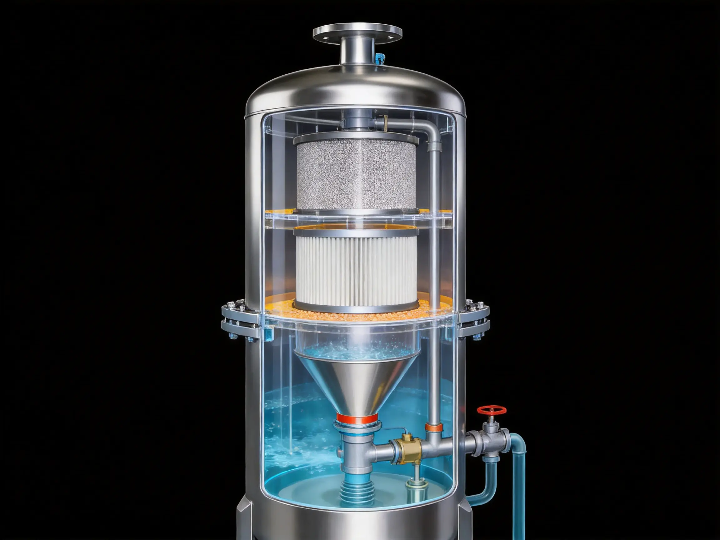
The first treatment stage uses cyclone separation to remove bulk liquid and relatively large solid particles from the compressed-air stream. As air enters the separator, its flow is redirected into a controlled rotating movement. Centrifugal force drives heavier oil droplets, water droplets, and particles toward the internal wall of the vessel. These contaminants lose momentum, collect, and move downward under gravity.
Cyclone separation is valuable because it removes a significant contaminant load before the air reaches the filter elements. The filter media therefore does not have to handle all of the liquid and solid material directly. This can extend filter service life, reduce premature blockage, and help maintain a stable pressure drop. The separation of bulk liquid at the beginning of the process also improves the working conditions for the downstream pre-filter and fine filter.
Unlike a single-stage depth filter, a cyclone separator does not rely exclusively on a delicate filter medium to capture large droplets. Its mechanical operating principle supports continuous industrial use and is less sensitive to a temporary increase in bulk liquid loading. For facilities with variable compressor loads or humid ambient conditions, this initial separation function can provide an important level of protection.
Stage Two: Pre-Filtration
After cyclone separation, the air passes through a pre-filtration stage. This stage captures remaining liquid droplets, larger oil aerosols, and coarse particulate matter. The pre-filter acts as a protective barrier for the final fine-filtration stage, reducing the concentration of contaminants that would otherwise accumulate on the finer media.
Pre-filtration is essential to a progressive purification design. If a fine filter is exposed directly to heavy contamination, its pores or fiber structure may become blocked quickly. The resulting pressure loss can rise rapidly, increasing compressor energy consumption and reducing available air delivery. By removing coarser contamination first, the pre-filter helps preserve the permeability and separation efficiency of the downstream element.
The pre-filtration stage also contributes to the removal of condensed oil and water. Depending on the operating conditions, the captured liquid can settle and be discharged through an appropriate drainage arrangement. The specific drain configuration should be selected and maintained according to the installation design, fluid load, and applicable safety procedures.
Stage Three: Fine Filtration
The final stage provides high-efficiency filtration for fine oil aerosols and small suspended particles. The fine filter is designed to capture contaminants that are too small or too light to be removed effectively by cyclone separation and coarse filtration. Through layer-by-layer filtration, the system can achieve a stated filtration accuracy of 0.1 micrometers.
Fine filtration may involve several mechanisms, including direct interception, inertial impaction, diffusion, and coalescence. The exact balance depends on the construction of the filter element and the characteristics of the air stream. Oil aerosols can combine into larger droplets within the filter structure, allowing them to move toward a collection region and be separated from the air. Fine particles are retained by the filter fibers or internal layers.
The three stages work as a coordinated system rather than as isolated components. Cyclone separation handles the heavier contaminant load, pre-filtration reduces the medium-size contamination burden, and fine filtration completes the purification process. This arrangement supports high cleanliness while helping to avoid the excessive pressure loss that can occur when a very fine filter is used alone.
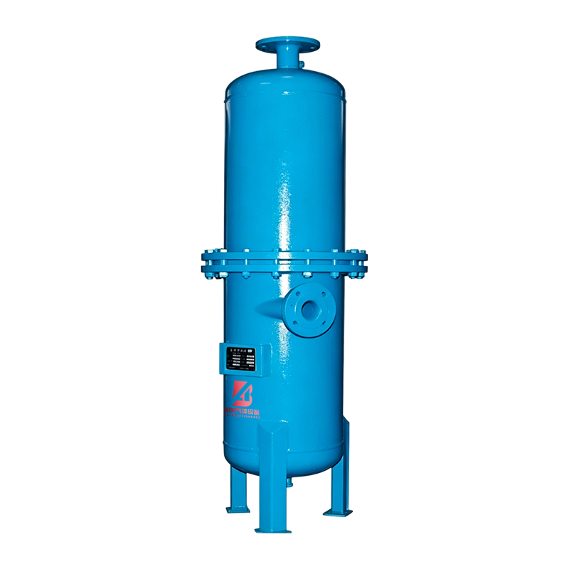
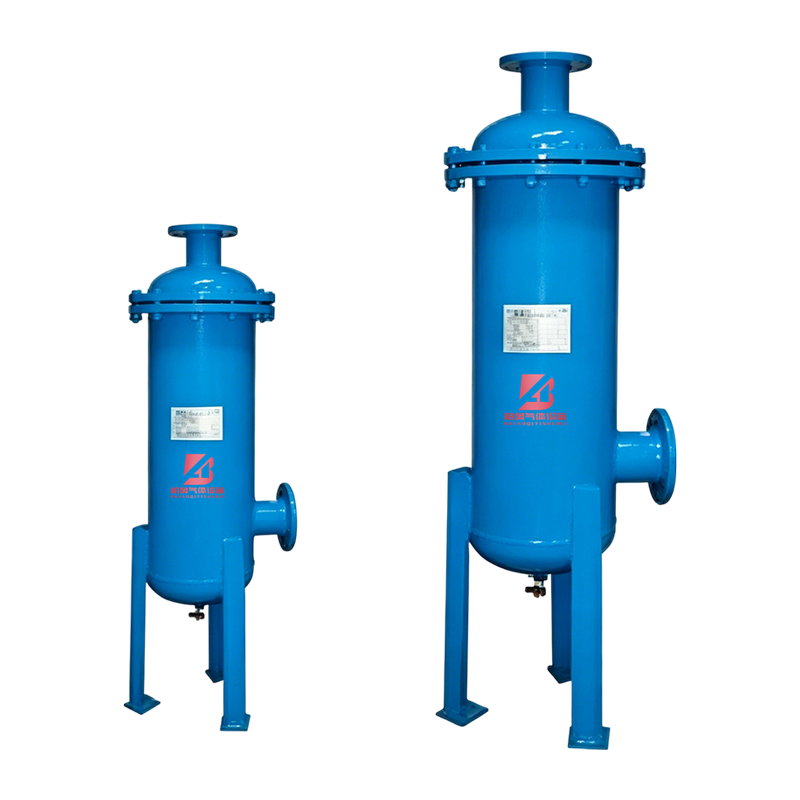
BDC High-efficiency Oil Remover
Key Performance Characteristics
Low Residual Oil Content
The principal purpose of the system is to reduce oil contamination in compressed air. The stated outlet oil content is within the range of 0.1 to 0.01 parts per million, with the product description specifying residual oil content below 0.01 parts per million under applicable conditions. Actual results depend on inlet contamination, air temperature, operating pressure, flow rate, filter condition, drainage performance, and correct installation.
Low residual oil content is important in processes where the air comes into contact with products, coatings, catalysts, membranes, optical surfaces, or sensitive electronic assemblies. It also helps protect downstream gas purification equipment. For example, oil carryover can foul adsorbents and reduce the performance of equipment used for nitrogen generation, oxygen generation, hydrogen purification, or other gas treatment processes.
Fine Filtration Accuracy
The stated filtration accuracy can reach 0.1 micrometers. This level of filtration is intended to remove fine suspended particles from the compressed-air stream. Cleaner air can improve the reliability of control instruments, pneumatic actuators, precision spray systems, and process equipment.
Filtration accuracy should always be considered together with flow rate and pressure conditions. A filter that performs well at its rated capacity may behave differently if it is overloaded. Correct model selection is therefore essential. The rated gas processing capacity table provides a starting point for matching the equipment to the air demand of a plant.
Low Pressure Loss
The stated pressure loss is no more than 0.02 MPa under the specified design conditions. Pressure loss matters because every unnecessary reduction in line pressure can increase compressor energy consumption or reduce the performance of pneumatic equipment. A purification unit with a balanced internal flow path can provide effective treatment without imposing an excessive burden on the compressor.
Pressure loss gradually changes as filters collect contaminants. Regular inspection and timely replacement of filter elements are necessary to keep the system within an efficient operating range. Monitoring inlet and outlet pressure, or using a differential-pressure indicator where appropriate, can help operators identify loading before it affects production.
Broad Operating Pressure Range
The standard operating pressure range is 0.4 to 1.0 MPa, with versions available for 1.0 to 3.0 MPa service. This range allows the product family to serve different compressed-air networks and process conditions. Users should confirm the required pressure class, connection design, vessel rating, safety requirements, and accessories before ordering a high-pressure version.
Controlled Inlet Temperature
The specified inlet air temperature is no more than 50°C. Temperature control is important because hot compressed air can affect oil viscosity, condensate behavior, filter media performance, seals, and the service life of internal components. An aftercooler or other suitable cooling arrangement may be required upstream when the compressor discharge temperature exceeds the recommended limit.
Operating within the stated temperature range also supports predictable condensation and coalescence behavior. If the air is too hot, liquid separation may be less effective because contaminants remain suspended as aerosols or vapor. If the air is cooled appropriately before purification, the separator and filters can perform more effectively.
Product Range and Capacity Selection
The product family includes models from BDC-1 through BDC-300. Rated gas processing capacity ranges from 1.2 to 330 Nm³/h according to the supplied parameter table. This wide range allows the same purification concept to be applied to small compressed-air installations, individual production machines, workshop systems, and larger centralized air networks.
Capacity selection should not be based only on the average air consumption. Designers should consider peak demand, compressor unloading cycles, future expansion, pressure requirements, inlet contamination, and the possibility of simultaneous operation of multiple users. Selecting a unit too close to the actual maximum flow may increase pressure loss and reduce filtration stability. A suitable design margin is normally considered during system engineering.
| Model | Rated gas processing capacity (Nm³/h) | Inlet and outlet diameter DN (mm) | Listed dimension values (mm) | Equipment weight (kg) |
| BDC-1 | 1.2 | 25 | Φ159; 880 × 418 × 45 | Not separately identified in the supplied row |
| BDC-2 | 2.4 | 25 | Φ159; 980 × 468 × 55 | Not separately identified in the supplied row |
| BDC-3 | 3 | 32 | Φ219; 1164 × 542 × 85 | Not separately identified in the supplied row |
| BDC-6 | 7.2 | 40 | Φ219; 1281 × 631 × 98 | Not separately identified in the supplied row |
| BDC-12 | 13.2 | 50 | Φ300; 1514 × 644 × 128 | Not separately identified in the supplied row |
| BDC-20 | 22 | 65 | Φ300; 1616 × 68 × 145 | Not separately identified in the supplied row |
| BDC-30 | 33 | 80 | Φ350; 1742 × 787 × 170 | Not separately identified in the supplied row |
| BDC-40 | 44 | 100 | Φ400; 1868 × 790 × 250 | Not separately identified in the supplied row |
| BDC-60 | 66 | 125 | Φ500; 1725 × 725 × 340 | Not separately identified in the supplied row |
| BDC-80 | 88 | 150 | Φ600; 1700 × 810 × 376 | Not separately identified in the supplied row |
| BDC-100 | 110 | 150 | Φ600; 1885 × 850 × 395 | Not separately identified in the supplied row |
| BDC-150 | 165 | 200 | Φ700; 1950 × 930 × 550 | Not separately identified in the supplied row |
| BDC-200 | 220 | 250 | Φ800; 2240 × 1160 × 645 | Not separately identified in the supplied row |
| BDC-300 | 330 | 300 | Φ1100; 2275 × 1180 × 750 | Not separately identified in the supplied row |
The supplied source table presents dimensional and weight fields in a compressed format, and some row values may require confirmation during technical quotation. Before fabrication or installation, buyers should request a final dimensional drawing, confirmed overall height and footprint, nozzle orientation, drain arrangement, maintenance clearance, and verified equipment weight for the selected model.
Advantages Compared with Single-Stage and Conventional Filtration
Progressive Contaminant Loading
A common weakness of basic filtration arrangements is that one filter element must remove bulk liquid, oil aerosols, and fine particles at the same time. This can cause rapid loading and a sharp increase in pressure loss. The integrated design distributes the contaminant load among three stages. As a result, each stage performs a more specialized function and the fine filter is better protected.
Improved Protection for Downstream Equipment
Many conventional separators are effective against liquid water but offer limited protection against fine oil aerosols. Some particle filters remove dust but do not adequately control oil. A combined cyclone, pre-filter, and fine-filter arrangement addresses liquid, aerosol, and particulate contamination in one treatment path. This is especially useful upstream of precision pneumatic systems and gas separation equipment.
Balanced Purification and Energy Performance
High filtration efficiency alone is not enough if the equipment creates excessive pressure loss. The stated pressure-loss value of no more than 0.02 MPa reflects a design emphasis on efficient air passage. Lower pressure loss can help reduce the need to raise compressor discharge pressure merely to compensate for treatment equipment. Over the operating life of a compressed-air system, this may support lower energy consumption, although actual savings depend on compressor efficiency, operating hours, pressure settings, and maintenance.
Scalable Model Selection
The broad model range is another advantage over products that are available only in a few fixed sizes. A facility can select a unit closer to its required flow rate, reducing the risk of severe oversizing or undersizing. The availability of larger models also supports centralized treatment for multiple production areas.
Adaptability to Industrial Gas Systems
Although the product is primarily described as an oil remover for compressed air, the purification concept is relevant to industrial gas preparation systems where upstream air cleanliness is important. Clean compressed air can improve the operating environment for nitrogen generators, oxygen generators, membrane systems, adsorption systems, and other gas purification units. The equipment can therefore function as an enabling component within a broader gas treatment plant.
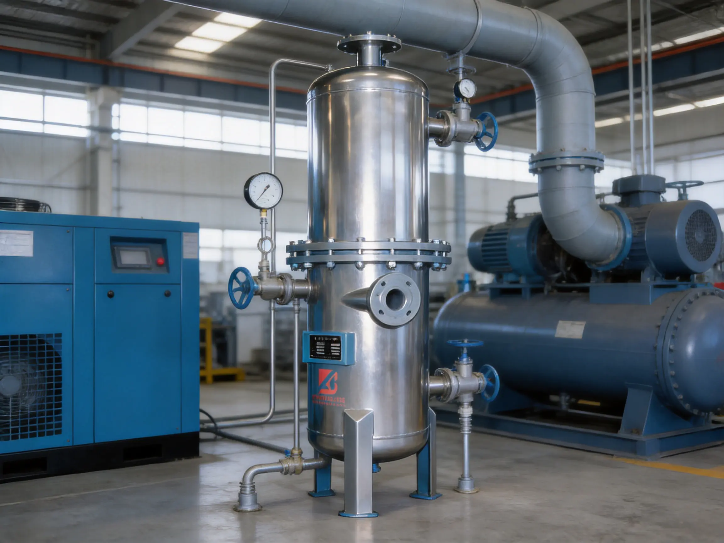
Manufacturing and Engineering Strengths
The equipment is produced by Zhejiang Baiao Gas Equipment Co., Ltd., a gas equipment manufacturer located in Fuyang District, Hangzhou, Zhejiang Province, China. The company integrates research and development, engineering design, production, installation, and after-sales service. This integrated structure is important for purification equipment because performance depends not only on the filter element but also on vessel design, flow distribution, connection configuration, drainage, installation, and commissioning.
Research and Development Integration
Gas purification products must be adapted to actual industrial conditions rather than designed only around laboratory performance. The company’s product scope includes PSA nitrogen generators, PSA oxygen generators, membrane nitrogen and oxygen generators, nitrogen purification units, and ammonia decomposition hydrogen purification equipment. Experience across these product categories can support a broader understanding of gas quality, pressure control, pretreatment, adsorption, separation, and process integration.
For the oil remover, this engineering perspective is relevant because upstream compressed-air cleanliness directly affects the service life and performance of downstream gas-generation equipment. Oil and water can damage adsorbents, contaminate membranes, and affect valves or switching systems. A manufacturer that works across separation and purification technologies can evaluate the oil-removal unit as part of a complete gas solution rather than as an isolated filter vessel.
Standardized Production Facilities
The company operates a standardized workshop of approximately 3,000 square meters, an office area of approximately 500 square meters, and a warehouse of approximately 500 square meters. These facilities provide space for equipment fabrication, component storage, assembly, inspection, documentation, and order preparation.
A dedicated workshop can improve production organization by separating raw-material handling, mechanical fabrication, assembly, testing, and finished-equipment storage. Proper warehouse management is also important for filter elements, seals, valves, gauges, and other components that must be protected from damage or contamination before installation.
Process Control from Design to Delivery
Integrated manufacturing allows technical information to move more directly from design to production. Customer requirements such as pressure class, capacity, nozzle size, installation orientation, and operating environment can be reviewed before fabrication. This reduces the risk of treating each order as a generic product when the application requires specific engineering consideration.
Quality control should cover materials, welding or vessel fabrication, internal component installation, sealing surfaces, connection dimensions, pressure integrity, cleanliness, and final appearance. For a purification system, internal cleanliness is particularly important. Residual welding debris, oil, dust, or metal particles inside the vessel could undermine the purpose of the equipment if not removed before dispatch.
Installation and After-Sales Support
The company provides installation and after-sales service as part of its business model. This is valuable because purification performance is affected by field conditions. Incorrect flow direction, insufficient upstream cooling, inadequate drainage, poor pipe support, or bypass leakage can reduce the effectiveness of even a well-designed filter.
Technical support can assist with model selection, layout planning, connection design, commissioning, operation training, and replacement planning. For international customers, clear manuals, dimensional drawings, spare-part information, and remote communication are important elements of a reliable service program.
Applications Across Industrial Sectors
Gas Generation and Air Separation
Air separation and gas-generation systems depend on clean feed air. PSA oxygen and nitrogen generators use adsorbent materials that can be adversely affected by oil and moisture. Pretreatment with an oil remover can reduce the contaminant load entering adsorption vessels and help protect valves and control instruments.
Membrane systems likewise require suitable feed-air quality. Oil aerosols and liquid water may foul membrane surfaces or alter separation performance. A properly selected oil-removal system can form part of the pretreatment package before membrane separation.
Petrochemical and Chemical Processing
Petrochemical facilities use compressed air for instruments, control valves, pneumatic tools, and process-support systems. Contamination can affect the response of control components and create maintenance problems in areas where reliable automation is essential. The oil remover can support cleaner instrument air and utility air when installed according to the plant’s pressure, temperature, and safety requirements.
Textile Manufacturing
Textile machinery often uses compressed air for weaving, spinning, cleaning, tension control, and automated handling. Oil contamination may stain fabric or interfere with air-operated components. Fine dust is also common in textile environments, making staged separation useful for protecting pneumatic equipment and improving air cleanliness.
Food and Beverage Processing
Compressed air may be used for packaging, filling, conveying, actuating, and cleaning. Where air is near a product or product-contact surface, oil and water contamination can create quality and hygiene concerns. The appropriate air-quality class and regulatory requirements must be confirmed for each application, but a high-efficiency oil-removal unit can provide an important part of the required treatment chain.
Automotive Manufacturing
Automotive plants use compressed air for assembly tools, paint spraying, robotic systems, metalworking, and cleaning. Oil carryover can affect paint adhesion and surface appearance, while moisture can contribute to corrosion and finish defects. A multi-stage purifier can support cleaner air for spray and process applications, provided that additional drying or specialty filtration is added when required.
Heat Treatment
Heat-treatment operations use gases and compressed air for furnace control, cooling, handling, and instrumentation. Stable air quality helps protect valves, analyzers, and control systems. Removing oil and water upstream can also reduce the risk of contamination entering other gas-treatment equipment.
SMT and Electronics Manufacturing
Surface-mount technology and electronics assembly require clean, stable compressed air for pick-and-place machines, soldering equipment, dispensing, cleaning, and pneumatic motion. Fine particles or oil aerosols can interfere with precision equipment and contaminate sensitive surfaces. The stated 0.1-micrometer filtration accuracy is relevant to applications where fine particulate control is important, subject to proper system sizing and verification.
Installation Recommendations
The oil remover should be installed in a position that allows safe access for inspection, drainage, and filter-element replacement. Adequate clearance should be provided around the vessel and connections. The foundation or support structure must be capable of carrying the operating weight and resisting vibration from nearby compressors and piping.
Flow direction must follow the product design. Incorrect installation can reduce separation efficiency and may cause abnormal pressure loss. Inlet and outlet piping should be properly supported so that excessive loads are not transferred to the equipment nozzles. Where the system is exposed to pulsation, vibration control or flexible connections may be appropriate.
The inlet air should be cooled sufficiently to remain within the maximum stated temperature of 50°C. If the compressor discharge is hotter than this limit, an aftercooler should normally be considered. The air line should also be arranged to prevent accumulated condensate from flowing unpredictably into the purification vessel.
Drainage is a critical part of liquid separation. Collected oil and water must be removed in accordance with the equipment design and local environmental requirements. A blocked or neglected drain can allow liquid to accumulate and become re-entrained in the air stream. Drain lines should be protected from freezing, mechanical damage, and accidental closure where applicable.
A bypass may be considered for maintenance continuity, but it should be designed carefully. An uncontrolled bypass can allow contaminated air to reach downstream equipment without the operator realizing it. Isolation valves, pressure gauges, differential-pressure monitoring, and warning labels can improve operational safety and maintenance visibility.
Maintenance and Operating Practices
Routine inspection should include inlet and outlet pressure, pressure loss, drain operation, visible leakage, unusual noise, corrosion, and the condition of external connections. A gradual increase in differential pressure generally indicates that filter elements are loading with contaminants. If pressure loss rises beyond the acceptable operating range, the elements should be inspected and replaced according to the maintenance plan.
Filter replacement intervals depend on air quality, flow rate, operating hours, compressor type, ambient dust, and the performance of upstream equipment. A fixed calendar interval may be convenient, but pressure-drop trends and actual operating conditions often provide a more reliable basis for service decisions.
Replacement elements should match the specified model and application. Improper filter media, incorrect dimensions, damaged seals, or poor installation can cause bypass leakage and reduce purification performance. During maintenance, the housing should be protected from dust and foreign material. All connections should be checked before returning the unit to service.
Operators should avoid treating the oil remover as a substitute for compressor maintenance. Excessive oil carryover may indicate worn compressor components, unsuitable lubricant, incorrect oil level, high operating temperature, or a damaged separator in the compressor package. The purifier is designed to remove contamination from the air stream, but correcting the source of abnormal contamination is essential for long-term reliability.
System records should include installation date, model, rated capacity, operating pressure, filter replacement date, differential pressure, drain inspections, and any abnormal events. Such records help identify trends and support preventive maintenance. They are also useful when planning capacity expansion or evaluating the condition of downstream gas-generation equipment.
How to Specify the Equipment for a Project
A technical inquiry should provide the required gas flow, normal and maximum pressure, inlet temperature, expected oil concentration, moisture conditions, ambient environment, connection size, installation altitude, and required outlet air quality. If the equipment will be installed before a nitrogen, oxygen, hydrogen, or membrane system, the feed-gas requirements of that downstream system should also be included.
The buyer should identify whether the rated flow is continuous, intermittent, or subject to short-term peaks. If several compressors operate in parallel, the maximum combined flow and compressor sequencing should be evaluated. A unit selected only for average flow may become overloaded during production peaks.
Space limitations should be communicated in advance. The listed model information includes vessel diameter and dimension values, but final drawings should confirm the actual footprint, height, nozzle positions, service clearance, lifting points, and maintenance access. The equipment weight should also be verified for transportation and foundation design.
For higher-pressure applications, the 1.0 to 3.0 MPa option should be clearly specified. Pressure ratings should not be assumed from the standard model. The manufacturer and purchaser should confirm the design pressure, test requirements, connection standard, safety accessories, and operating limits before production.
Why Manufacturer Capability Matters
Oil removal performance depends on the complete system, not only on the nameplate specification. A supplier with capabilities in research, design, fabrication, installation, and service can coordinate these factors more effectively. This is especially important when the equipment must be integrated into a custom gas plant or adapted to a customer’s existing compressed-air network.
Zhejiang Baiao Gas Equipment Co., Ltd. serves industrial sectors including petrochemical, textile, food processing, automotive manufacturing, heat treatment, and SMT electronics. Its products are sold across numerous regions in China and exported to international markets. This industrial exposure supports the development of equipment intended for practical operating environments rather than limited demonstration use.
The company emphasizes technical improvement, strict quality control, energy efficiency, integrity, and service. These priorities align with the needs of compressed-air users, who generally evaluate purification equipment according to more than initial purchase price. Long-term value also depends on pressure loss, filter life, spare-part availability, ease of maintenance, installation support, and compatibility with the rest of the gas system.
Q&A
What is the primary function of the high-efficiency oil remover?
Its primary function is to remove oil, water, and dust from compressed air. It uses cyclone separation, pre-filtration, and fine filtration to treat the air progressively and reduce contamination before the air reaches downstream equipment.
What filtration accuracy can the system achieve?
The supplied product information states that the filtration accuracy of treated compressed air can reach 0.1 micrometers. Actual performance depends on model selection, flow rate, pressure, temperature, inlet contamination, filter condition, and correct installation.
What residual oil content is specified?
The technical information gives an outlet oil-content range of 0.1 to 0.01 ppm and states that residual oil content can be less than 0.01 ppm. The precise result should be confirmed for the selected model and operating conditions.
What operating pressure is supported?
The standard operating pressure is 0.4 to 1.0 MPa. Versions for 1.0 to 3.0 MPa are available according to the supplied information. High-pressure requirements should be confirmed during technical selection.
What is the maximum inlet air temperature?
The stated inlet air temperature limit is no more than 50°C. If compressor discharge air exceeds this value, an aftercooler or another suitable cooling arrangement may be required upstream.
What pressure loss should users expect?
The stated pressure loss is no more than 0.02 MPa under the specified operating conditions. Pressure loss can rise as filter elements become loaded, so regular monitoring and timely replacement are important.
How should the capacity be selected?
Capacity should be selected based on maximum expected flow rather than only average consumption. Peak demand, future expansion, compressor operation, pressure, temperature, and inlet contamination should all be considered. The model range covers rated capacities from 1.2 to 330 Nm³/h in the supplied table.
Can the oil remover be used before a PSA nitrogen or oxygen generator?
It can be considered as a pretreatment component before gas-generation equipment, provided that the pressure, flow, temperature, air-quality, and connection requirements are compatible. The downstream generator manufacturer’s feed-air requirements should always be checked.
Does the system eliminate the need for a dryer?
Not necessarily. The oil remover separates water droplets and contributes to moisture removal, but it is not automatically a replacement for a refrigerated dryer, desiccant dryer, membrane dryer, or other dedicated drying system. The required dew point should determine whether additional drying equipment is needed.
How often should the filter elements be replaced?
Replacement frequency depends on inlet air quality, operating hours, flow, temperature, compressor condition, and pressure-drop trends. Users should monitor differential pressure and follow the manufacturer’s maintenance recommendations instead of relying on a universal replacement interval.
What information should be supplied when requesting a quotation?
Important information includes required flow, working pressure, inlet temperature, compressor type, expected contamination, connection diameter, installation location, required outlet air quality, ambient conditions, and whether the unit will be integrated with a gas generator or air separation system.
Why is the three-stage design preferable to a single filter?
The three-stage arrangement assigns different duties to cyclone separation, pre-filtration, and fine filtration. This reduces the burden on the fine filter, supports more stable pressure loss, improves liquid and particle removal, and provides more comprehensive treatment than a single general-purpose filter.
Conclusion
The high-efficiency oil remover provides a practical solution for treating contaminated compressed air in industrial environments. Its integrated cyclone separator, pre-filter, and fine filter address bulk liquid, oil aerosols, and fine particles in sequence. The stated performance includes filtration accuracy down to 0.1 micrometers, residual oil content as low as less than 0.01 ppm under applicable conditions, operating pressure from 0.4 to 1.0 MPa as standard, optional pressure service up to 3.0 MPa, inlet temperature up to 50°C, and pressure loss no greater than 0.02 MPa under specified conditions.
Compared with a single-stage filtration arrangement, the progressive design offers better contaminant-load distribution and stronger protection for downstream equipment. The broad model range supports applications from compact air systems to larger industrial installations. Proper sizing, cooling, drainage, installation, monitoring, and filter replacement are essential to achieving the expected performance.
Backed by a manufacturer that combines research and development, engineering design, fabrication, installation, and after-sales service, the equipment can be configured for a range of compressed-air and gas-purification applications. Its role is especially important in air separation, gas generation, petrochemical production, food processing, automotive manufacturing, heat treatment, textiles, and electronics. When incorporated into a correctly designed treatment chain, it can help improve air quality, protect valuable process equipment, reduce contamination-related maintenance, and support more stable industrial production.
References
Compressed Air and Gas Institute. Compressed Air System Design and Maintenance Principles.
International Organization for Standardization. Compressed Air—Contaminants and Purity Classes.
International Organization for Standardization. Air Quality Requirements for Compressed-Air Treatment Equipment.
U.S. Department of Energy. Improving Compressed Air System Performance: A Sourcebook for Industry.
Industrial filtration engineering literature covering cyclone separation, coalescing filtration, aerosol capture, and differential-pressure monitoring.
Manufacturer-supplied technical information for the high-efficiency oil remover product range, including operating conditions, performance specifications, and model parameters.
Product: BDC High-efficiency Oil Remover


- Tel: +86-15057127179
+86-13588382771 - Email: huang.yifan0215@gmail.com
- Address: Huanshan Township, Fuyang District, Hangzhou City, Zhejiang Province
Copyright © Zhejiang Baiao Gas Equipment Co., Ltd. All Rights Reserved.
Privacy
Gas Generator Plant Manufacturer, Industrial Purification Equipment Plant
