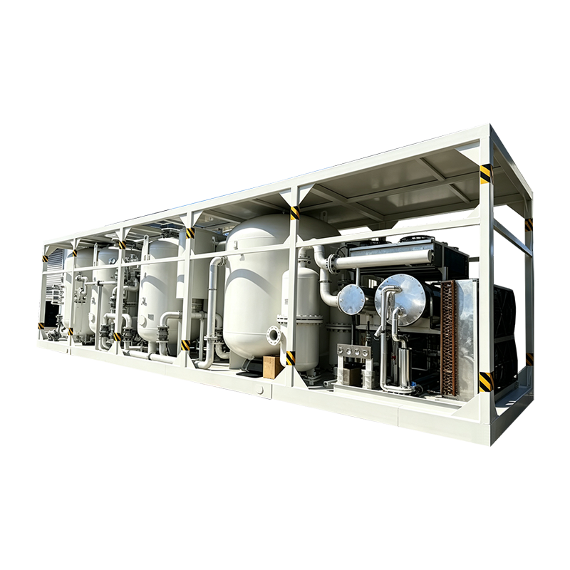
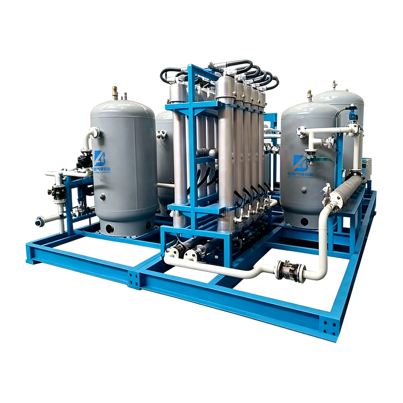
Helium Recovery Solution
I. General Principles of the Solution
1.1 Background
Helium is a non-renewable strategic rare inert gas with ultra-low boiling point, stable chemical properties and excellent permeability, which is widely used in high-end manufacturing, medical scientific research, aerospace, precision testing and other core industries. At present, China’s import dependence on helium exceeds 95%. Frequent import price fluctuations and unstable gas supply, together with direct venting and low utilization rate in traditional processes, greatly increase enterprise production costs and restrict the stable operation of high-end industrial production.
With the maturity of localized helium recovery and purification technology, 5N high-purity helium recovery equipment has achieved full independent controllability, and 6N ultra-high-purity closed-loop recovery equipment has been mass-produced. Adopting a closed-loop model of recovery, purification and recycling, the system effectively reduces the procurement volume of virgin helium, and achieves comprehensive values of cost reduction, efficiency improvement, stable gas supply, production guarantee and green low-carbon production.
1.2 Applicable Scenarios
This solution covers five typical helium application scenarios and adapts to different gas purity standards, waste gas impurity conditions and discharge characteristics:
- Semiconductor Manufacturing: EUV lithography, wafer etching, thin film deposition, equipment cooling and pipeline leak detection (requiring 6N ultra-high-purity helium).
- Medical Superconducting Scientific Research: Cryogenic cooling of MRI superconducting magnets, quantum computing, particle accelerators and superconducting experiments (closed-loop recycling of liquid helium and high-purity helium gas).
- Industrial Precision Testing: Helium mass spectrometer leak detection for auto parts, pressure vessels, vacuum pipelines and new energy equipment (5N high-purity helium; exhausted gas contains air and water vapor impurities).
- Aerospace & Defense Industry: Rocket fuel tank pressurization, pipeline purging, cryogenic system cooling, wind tunnel aerodynamic testing, and precision temperature control of missile components.
- Optical Fiber & High-End Manufacturing: Carrier gas for OVD/VAD deposition of optical fiber preforms, shielding gas for precision welding of high-end alloys.
1.3 Objectives of the Solution
- Recovery Efficiency: The comprehensive helium recovery rate reaches no less than 85% for general scenarios, and 90%–95% for high-end precision scenarios (semiconductor, MRI).
- Purification Precision: Stable 5N (99.999%) high-purity helium output for industrial leak detection and welding scenarios; 6N (99.9999%) ultra-high-purity helium output for semiconductor and scientific research scenarios.
- Cost Reduction: Reduce the procurement of virgin helium by 60%–90% and hedge the risk of helium price fluctuation.
- System Stability: Support 24-hour continuous closed-loop operation, adapt to uninterrupted production, with low O&M cost and high localization compatibility.
II. Pain Point Analysis of Helium Loss in Various Scenarios
2.1 Semiconductor Manufacturing Scenario
As a typical ultra-high-purity gas application scenario, EUV lithography and wafer fabrication require continuous supply of 6N ultra-high-purity helium for cooling, dust removal and inert protection. Process tail gas is discharged with trace water vapor, oxygen, dust and organic impurities. The traditional direct venting mode causes massive helium loss. A single high-end device consumes tens of thousands of liters of helium annually, resulting in extremely high procurement costs of ultra-high-purity helium.
2.2 Medical Superconducting MRI Scenario
Liquid helium is adopted for cryogenic refrigeration of superconducting magnets. Helium loss mainly comes from vaporization leakage, maintenance venting and cooling depressurization venting. The exhausted gas features high purity and few impurities, but scattered long-term discharge causes severe cumulative waste. Traditional operation has no recovery system and fully relies on purchased liquid helium for supplementation.
2.3 Industrial Helium Leak Detection Scenario
This scenario features the largest helium consumption and most scattered loss. After leak detection, residual helium mixes with a large amount of air, water vapor and oil pollutants with unstable concentration and dispersed discharge. Most enterprises directly vent the mixed gas, leading to a helium utilization rate lower than 20% and serious resource waste.
2.4 Aerospace Scenario
Helium is mainly used for high-pressure purging, system pressurization and cryogenic cooling, characterized by high working pressure and large instantaneous discharge volume. Tail gas contains trace fuel residue, dust and air impurities. Concentrated discharge during tests and maintenance leads to huge one-time helium consumption without recycling systems.
2.5 Optical Fiber Manufacturing & Precision Welding Scenario
In optical fiber preform production, helium serves as carrier gas and continuously carries process waste gas. In precision welding, helium acts as shielding gas to isolate air and prevent weld oxidation. Continuous discharge of impurity-containing tail gas causes stable and long-term helium loss, maintaining high annual helium consumption per production line.
III. Overall Recovery System Architecture & Core Process
This solution adopts an integrated architecture of Centralized Collection + Graded Pretreatment + Fine Purification + Pressurized Storage + Closed-Loop Reuse. Customized process modules are configured according to tail gas impurity concentration and gas purity requirements to realize full-scenario adaptive helium recovery.
3.1 Overall System Flow
Waste Gas Collection → Pressure Stabilization & Buffering → Coarse Filtration (Dust & Oil Removal) → Cryogenic Dehydration & Drying → Membrane Separation Purification → Precision Detection → Pressurization & Compression → Low-temperature Liquefaction / High-pressure Gas Storage → Closed-Loop Reuse
3.2 Core Unit Process Descriptions
3.2.1 Centralized Waste Gas Collection Unit
Dedicated collection pipelines are deployed for different working conditions. Continuous production scenarios (semiconductor, optical fiber production lines) adopt fully closed negative-pressure pipeline collection; intermittent gas consumption scenarios (helium leak detection, aerospace testing, MRI maintenance) adopt flexible collection hoods matched with negative-pressure buffer tanks to eliminate unorganized emission, achieving a waste gas collection rate above 98%. All pipelines adopt stainless steel seamless pipes to avoid impurity adsorption and helium leakage loss.
3.2.2 Pretreatment & Purification Unit
This unit performs preliminary purification for tail gas containing particulate matter, oil stains and water vapor, adapting to industrial detection, aerospace and welding scenarios with complex impurities. Tail gas passes through primary dust filters, precision oil removal filters and cryogenic drying towers in sequence to remove dust, oil and moisture, reducing particulate and water vapor content below 1 ppm and lowering the purification load of downstream membrane separation units.
3.2.3 Deep Purification Unit (Core Module)
This solution adopts membrane separation technology as the core process with auxiliary fine post-treatment, completely replacing the traditional PSA and cryogenic distillation composite process. With high automation, low energy consumption and no adsorbent consumables, the system supports 24-hour stable continuous operation and is the most mature and mainstream technology for industrial helium recovery. Based on polymer selective permeation membranes and driven by transmembrane gas partial pressure difference, the system separates helium from air, water vapor, nitrogen, oxygen and oil impurities according to molecular size and permeation rate differences, realizing graded purification to 5N/6N high-purity helium to meet multi-scenario gas supply standards.
3.2.3.1 Core Separation Principle of Membrane Separation Technology
Helium molecules feature ultra-small kinetic diameter and extremely high permeation coefficient. Under pressure driving force, helium can rapidly penetrate dedicated helium separation membranes, while large-molecule and high-boiling impurities such as nitrogen, oxygen, water vapor and carbon dioxide are intercepted by the membrane. The whole separation process is a pure physical screening and permeation procedure without chemical reaction or phase change. Operating at ambient temperature, the process will not change the physical and chemical properties of helium and produces no secondary pollution.
The gas permeation rate ranking is: He > H₂ > O₂ > N₂ > H₂O > Oil and Gas Impurities. This characteristic ensures efficient interception of most impurities and high-efficiency enrichment of high-purity helium.
3.2.3.2 Dedicated Membrane Material Selection & Characteristics
The system is equipped with localized polyimide hollow fiber helium separation membranes, professional high-end membrane materials dedicated to helium recovery, adapting to complex tail gas working conditions. The core advantages are as follows:
- High Selectivity: High helium screening accuracy and large permeation flux, with impurity rejection rate ≥ 99% for stable high-purity helium output.
- Strong Anti-Pollution Performance: Resistant to oil, water vapor and dust pollution, avoiding membrane blockage and aging for complex industrial tail gas conditions.
- High Operational Stability: Ambient temperature and pressure operation without high/low temperature auxiliary equipment. Long membrane service life and no frequent consumable replacement, ensuring ultra-low O&M cost.
- Modular Adaptability: Support series and parallel modular combination to adapt to intermittent small-flow and continuous large-flow gas consumption scenarios.
3.2.3.3 Graded Purification Process of Membrane Separation
According to different tail gas impurity concentrations, a multi-stage series membrane separation process is adopted with front-end pretreatment and back-end fine treatment for gradient purification. The standard process is: Pretreatment (Oil, Water & Dust Removal) → Primary Membrane Separation (Primary helium enrichment, bulk N₂/O₂ removal) → Secondary Membrane Fine Separation (deep removal of trace gaseous impurities) → Post Deoxidation & Drying Treatment → High-Purity Helium Output.
Differentiated configuration: Double-stage membrane separation stably outputs 5N high-purity helium for industrial leak detection, optical fiber and welding scenarios; three-stage membrane separation matched with trace impurity fine treatment produces 6N ultra-high-purity helium for semiconductor, MRI and high-end scientific research scenarios.
3.2.3.4 Core Advantages & Scenario Adaptation Rules
Compared with traditional PSA adsorption and cryogenic distillation, membrane separation equipment features simple structure, small footprint and fast start-up, supporting 24-hour unattended continuous operation. It reduces energy consumption by more than 30% without valve switching loss or adsorbent regeneration procedure, effectively avoiding purity fluctuation caused by adsorbent aging and pulverization. The modular design supports flexible capacity expansion and is suitable for new and renovated production lines.
Scenario Adaptation: Pure membrane separation process is adopted for industrial leak detection, optical fiber manufacturing, precision welding and conventional aerospace testing for optimal cost performance and minimal maintenance. For semiconductor and medical superconducting ultra-high-purity scenarios, the composite process of membrane separation + trace impurity fine treatment is applied to balance recovery efficiency and ultra-high purity, achieving a comprehensive recovery rate of 85%–95%.
3.2.3.5 Technology Comparison: Membrane Separation vs. Traditional Processes
Traditional PSA adsorption relies on adsorbent impurity capture, requiring regular regeneration and consumable replacement with unstable purity and heavy maintenance workload. Cryogenic distillation requires low-temperature phase-change conditions, with high equipment investment and extreme energy consumption, only applicable to ultra-large-scale high-purity projects. In contrast, membrane separation adopts full ambient-temperature physical separation with no consumable replacement, no high energy consumption, stable operation and wide adaptability, becoming the optimal solution for multi-condition and full-scenario helium recovery.
3.2.4 Detection & Storage Unit
Online gas chromatographs and trace moisture/oxygen analyzers are equipped for real-time detection of helium purity and impurities. Unqualified gas automatically flows back for re-purification, while qualified helium is pressurized by booster units. Two storage modes are available: cryogenic liquid helium storage tanks for medical superconducting scenarios, and high-pressure ambient-temperature gas storage tanks for industrial and semiconductor scenarios, realizing on-demand stable gas supply for production reuse.
3.2.5 Intelligent Automatic Control Unit
The PLC intelligent control system automatically adjusts collection negative pressure, purification pressure, temperature and flow rate. It realizes real-time monitoring of system operating parameters, helium recovery rate and gas purity, and integrates overload protection, leakage alarm, fault automatic shutdown and data traceability functions to support long-term unattended stable operation.
IV. Customized Recovery Solutions by Scenario
4.1 Semiconductor Ultra-High-Purity Helium Recovery Solution
Applicable Conditions: EUV lithography, wafer etching and thin film deposition processes. Tail gas has few impurities and high initial helium purity, requiring zero-contamination 6N ultra-high-purity helium output.
Customized Process: Fully sealed pipeline collection → Precision dust removal and drying → Membrane separation deep purification → Trace impurity fine treatment → Online high-precision detection → High-pressure closed-loop gas supply.
Core Parameters: Helium recovery rate ≥ 92%, output purity 99.9999%, water vapor and oxygen content ≤ 0.1 ppm. Fully compatible with advanced semiconductor process equipment, reducing virgin helium procurement by over 80%.
4.2 Medical MRI Superconducting Liquid Helium Recovery Solution
Applicable Conditions: Vaporized helium from superconducting magnet operation and maintenance depressurization venting, with high gas cleanliness and no complex impurities, focusing on liquid helium closed-loop recycling.
Customized Process: Sealed collection of magnet depressurization tail gas → Pressure stabilization and buffering → Precision drying and filtration → Membrane separation purification → Helium re-liquefaction → Cryogenic liquid helium storage → Reflux reuse for magnets.
Core Parameters: Liquid helium recovery rate ≥ 95% with negligible quality loss, effectively reducing hospital liquid helium procurement frequency and O&M cost and eliminating traditional venting waste.
4.3 Industrial Helium Leak Detection Universal Recovery Solution
Applicable Conditions: Parts and pressure vessel leak detection. Tail gas contains mixed air, water vapor and oil stains with fluctuating helium concentration and dispersed discharge.
Customized Process: Negative-pressure flexible collection → Oil and water coarse removal → Multi-stage membrane separation purification → Precision detection → Pressurized storage and reuse.
Core Parameters: Comprehensive recovery rate ≥ 85%, stable 5N high-purity helium output, fully meeting industrial leak detection standards and adapting to batch continuous production lines.
4.4 Aerospace High-Pressure Helium Recovery Solution
Applicable Conditions: System purging, pressurization and cryogenic testing, featuring intermittent operation, high pressure and instantaneous large-flow discharge, with trace dust and fuel residue in tail gas.
Customized Process: High-pressure buffer collection → Explosion-proof filtration and purification → Multi-stage membrane separation and pressure stabilization → High-pressure boosting storage → Cyclic reuse for testing.
Core Parameters: Adaptable to high-pressure instantaneous working conditions with recovery rate ≥ 88%. Equipment meets explosion-proof and high-pressure resistance requirements and aerospace military safety standards.
4.5 Optical Fiber Manufacturing & Precision Welding Recovery Solution
Applicable Conditions: 24-hour continuous production with stable-flow tail gas containing process oxidation impurities and sustained helium loss.
Customized Process: Continuous pipeline sealed collection → Impurity filtration and drying → Membrane separation purification → Stabilized pressure closed-loop gas supply.
Core Parameters: Recovery rate ≥ 90%, stable 5N high-purity helium output, adapting to uninterrupted production and effectively reducing continuous helium consumption loss.
V. Core Equipment Selection (Localized Standard Configuration)
|
System Unit
|
Core Equipment
|
Applicable Scenario
|
Equipment Advantages
|
|
Collection Unit
|
Negative pressure fan, stainless steel sealed pipeline, flexible collection hood, buffer gas tank
|
All scenarios
|
Zero leakage, corrosion resistance, compatible with continuous and intermittent gas consumption
|
|
Pretreatment Unit
|
Primary filter, precision oil removal filter, cryogenic drying tower
|
Industrial, aerospace and welding scenarios
|
Efficient removal of dust, oil and moisture, protecting downstream membrane elements
|
|
Purification Unit (Core)
|
Multi-stage membrane separation module, catalytic deoxidation unit, fine impurity treatment unit
|
Full-scenario adaptation
|
Localized independent technology, adjustable 5N/6N precision, low energy consumption, no adsorbent consumables
|
|
Storage Unit
|
High-pressure helium storage tank, cryogenic liquid helium tank, booster compressor
|
Industrial gas storage / Medical liquid helium storage
|
Precise pressure maintenance, ultra-low gas loss, suitable for closed-loop recycling
|
|
Detection & Control Unit
|
Online gas chromatograph, trace moisture/oxygen analyzer, PLC intelligent control system
|
All scenarios
|
Real-time monitoring, automatic adjustment, unattended operation, traceable operating data
|
VI. System Operation, Maintenance & Safety Assurance
6.1 Routine O&M Specifications
- Daily Inspection: Check pipeline tightness, equipment operating pressure, temperature and gas purity data to eliminate leakage risks.
- Regular Maintenance: Replace filter consumables monthly, clean drying tower impurities quarterly, calibrate detection instruments and overhaul booster equipment regularly.
- Consumable Management: Replace filter elements and auxiliary consumables as required to ensure stable purification accuracy.
6.2 Safety Protection Measures
- Helium is an inert gas. The whole system adopts fully closed operation, equipped with hypoxia alarm, overpressure relief and explosion-proof devices to eliminate potential safety hazards.
- All equipment is statically grounded, and pipelines adopt pressure-resistant and explosion-proof design to adapt to industrial and aerospace high-risk working conditions.
- An emergency venting loop is configured to automatically cut off the closed-loop system in case of failure to ensure production safety.
6.3 Fault Emergency Mechanism
The system supports automatic fault diagnosis. In case of substandard purity, abnormal pressure or equipment overload, it will trigger an alarm and switch to emergency mode automatically. Unqualified gas will be returned for re-purification without affecting normal production gas supply, ensuring production continuity.
VII. Solution Benefit Analysis
7.1 Economic Benefits
Closed-loop helium recycling reduces virgin helium procurement by 60%–95% and effectively hedges import price fluctuation risks. For large-scale scenarios such as 12-inch wafer fabs, industrial helium leak detection workshops and hospital MRI centers, the system can reduce annual helium cost by hundreds of thousands to tens of millions of RMB, with a typical investment payback period of 1–3 years, delivering long-term significant cost reduction benefits.
7.2 Supply Chain Benefits
The system reduces high reliance on imported helium and realizes self-sufficient helium circulation. It avoids production suspension risks caused by geopolitical changes and helium shortage, guarantees stable operation of high-end manufacturing, medical research and aerospace industries, and improves enterprise supply chain autonomy and security.
7.3 Environmental & Social Benefits
As a non-renewable strategic resource, helium recycling greatly reduces resource waste and lowers carbon emissions and energy consumption in helium exploitation and transportation. The solution conforms to green low-carbon development concepts and supports national strategic resource conservation and industrial security layout.
VIII. Summary & Implementation Recommendations
Based on the helium consumption characteristics and waste loss pain points of five mainstream application scenarios, this solution adopts mature localized membrane separation recovery technology to build a modular, customizable and intelligent closed-loop helium recycling system. Compatible with ordinary industrial and ultra-high-purity semiconductor/scientific research gas demands, the system features high recovery efficiency, stable operation and low maintenance cost, delivering prominent economic, safety and environmental benefits. It is the optimal long-term solution for enterprises to solve high helium cost and gas supply shortage problems.
Implementation Recommendations: Prioritize renovation of production lines with large helium consumption and serious direct venting waste. Configure modular equipment according to actual gas flow, purity requirements and working conditions for step-by-step promotion and full coverage. Establish standardized routine maintenance and data monitoring mechanisms to maximize helium recovery efficiency and system service life.

 en
en русский
 Español
 عربى
عربى